|
|
Zeus Power AmplifiersA Zero Feedback Power Amplifier
General Amplifier Schematic Amplifier Highlights
Zeus System - Pre + PowerFull end to end configuration with TX-102 TVC input.
Zeus-75Class A (AB) monoblock power amplifier with separate PSU.
Zeus 75 Amplifier and Power Supply Concept CAD Image
Zeus 75 Distortion versus Power Output. Use with 4 ohm impedance speakers with 2:1 step down output is not normally recommended but this graph is to demonstrate the amplifier operation where distortion level plateaus at 1% (unlike conventional amplifiers where it would continue to rise). Power at maximum output is over 100 watts. Note: Full Class A or Class AB operation depends on output transformer configuration, mosfet bias level and load being driven.
Zeus Pre-amp / Line DriversSE and PP pre-amplifier variations.
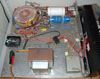
Zeus 35 Monoblock Power AmplifierMy original prototype power amplifier.
Original Zeus 35 Amplifier Internal View - One of a Pair.
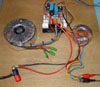
Additional Experimental InformationThese pages show examples of what can be done with the Zeus topology.
|


All design and other information, drawings and images on this website
are
Copyright © 1992-2010
Susan Parker MIET (unless otherwise credited).
These designs and other information may be used to construct systems specifically for personal NON commercial use only.
N.B. Personal liability disclaimer applies - see T&C.